Mitsubishi QJ71C24N Modbus RTU Communication with Siemens Sinamics V20 Tutorial
Introduction
This comprehensive guide will walk you through the process of using a Mitsubishi Q-Series PLC equipped with the QJ71C24N communication module to control and monitor a Siemens Sinamics V20 inverter via the Modbus RTU protocol. This tutorial is designed to be simple and straightforward, making it accessible even for those new to this setup.
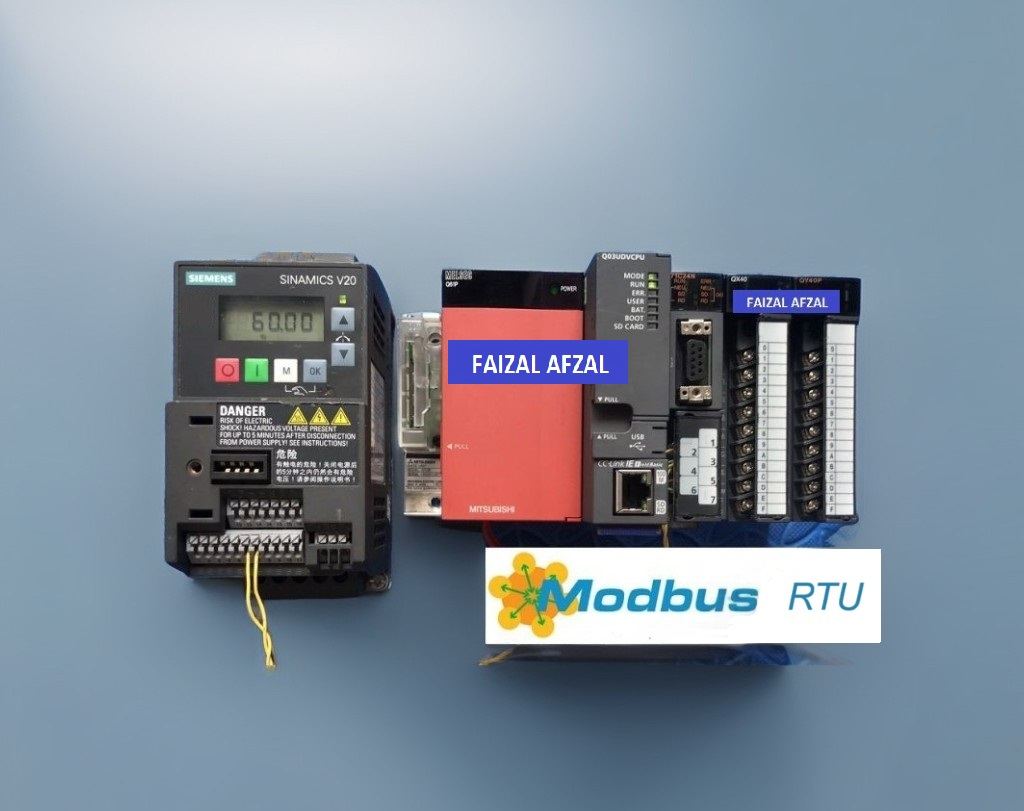
1. QJ71C24N & Sinamics V20: Connection Diagram
The Siemens Sinamics V20 inverter comes with a built-in RS485 communication port, enabling easy and direct connection to the Mitsubishi QJ71C24N module.
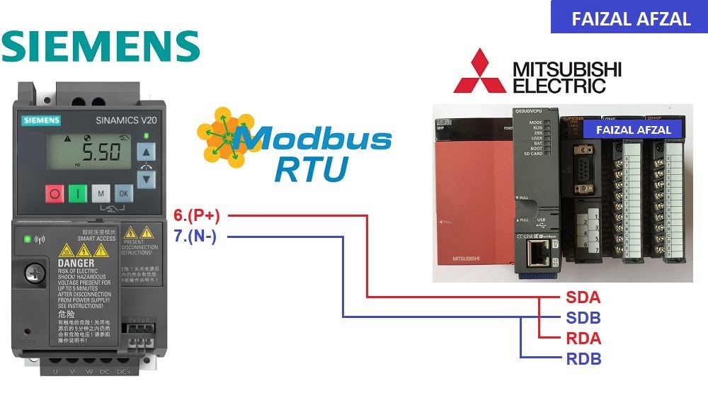
Connection Diagram between QJ71C24N and Sinamics V20
Explanation:
- RS485 Communication Port: The built-in RS485 port on the Siemens V20 allows seamless integration with the QJ71C24N module.
- Wiring Configuration: Ensure that the correct wiring is used to establish a reliable communication link between the devices.
2. Siemens Sinamics V20 Modbus RTU Configuration
To control and monitor the Siemens Sinamics V20 inverter using Modbus RTU, it is necessary to configure specific communication parameters in addition to the standard inverter settings such as frequency, current, and voltage.
Key Configuration Steps:
- VFD Control Address:
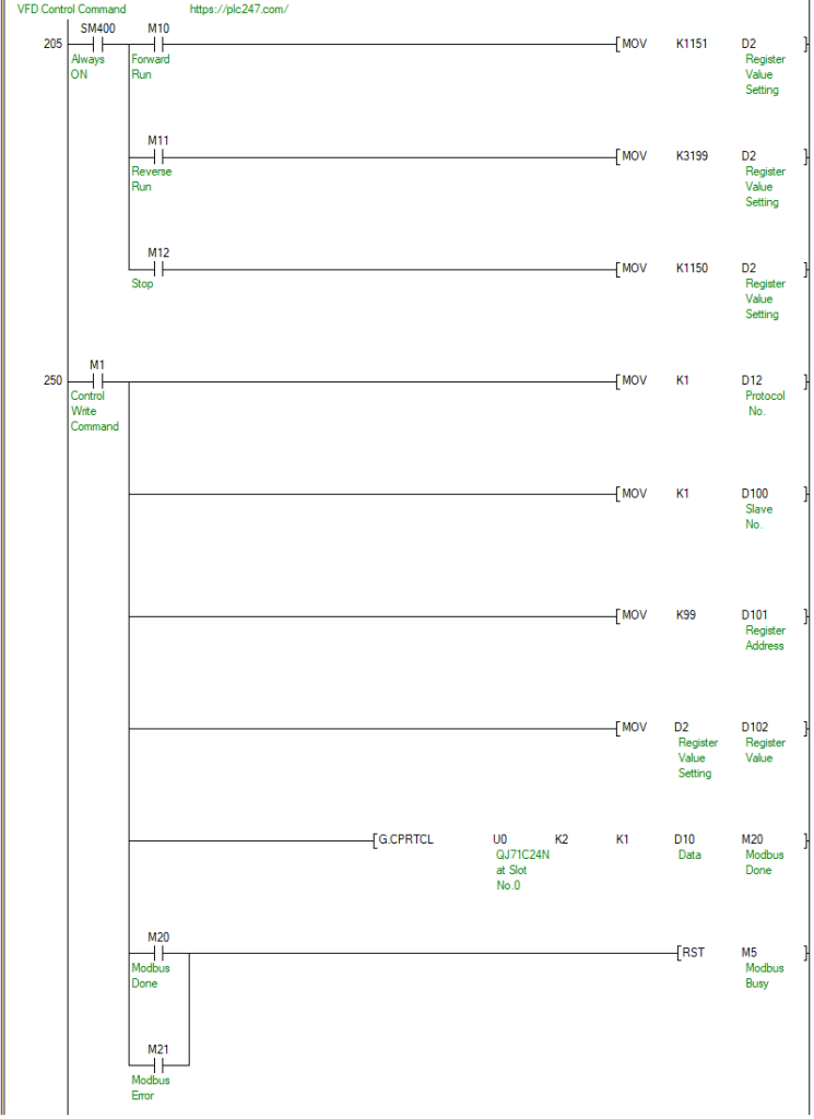
99 (dec)- Set Word 40100 = 1151 >>> Forward Run
- Set Word 40100 = 3199 >>> Reverse Run
- Set Word 40100 = 1150 >>> Stop
- Set Word 40100 = 1278 >>> VFD Reset
- VFD Frequency Reference Address:
100 (dec)- Speed Reference Range: “0 to 100%” = “0 to 16384 dec”
- Monitoring Addresses:
- Frequency Output Address:
23 (dec) - Speed Output Address:
24 (dec) - Current Output Address:
25 (dec)
- Frequency Output Address:
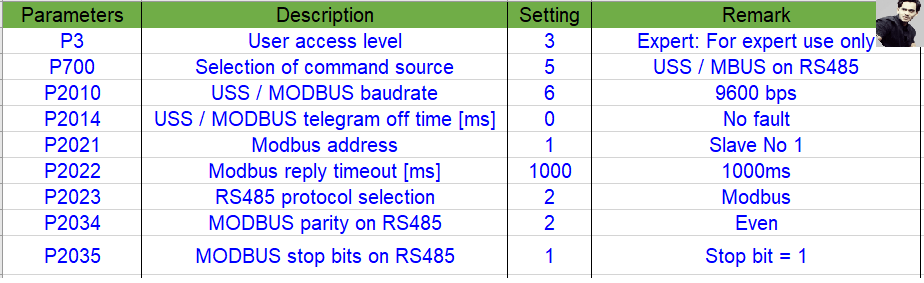
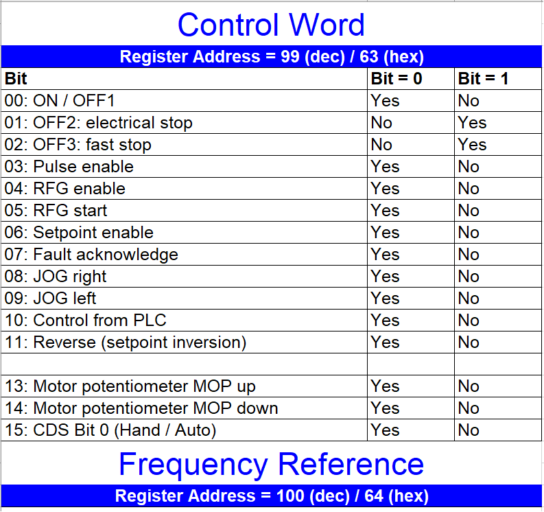
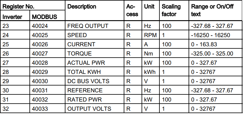
Siemens Sinamics V20 Modbus RTU Configuration
3. QJ71C24N Modbus RTU Parameters Setting
The next step involves configuring the QJ71C24N module to communicate effectively with the Siemens V20 via Modbus RTU.
Step-by-Step Configuration:
- Step 1: Create New Project
- Start by creating a new project in your Mitsubishi PLC programming environment, tailored to your specific PLC model.
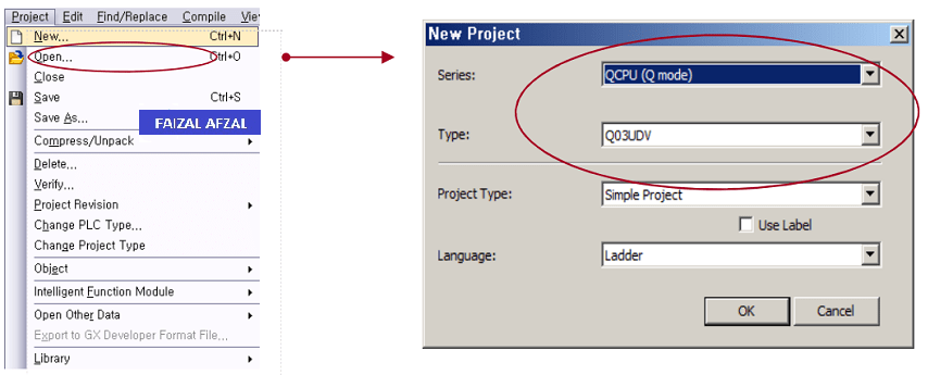
- Step 2: I/O Configuration
-
- Properly configure the I/O settings to include the QJ71C24N module within your PLC setup.
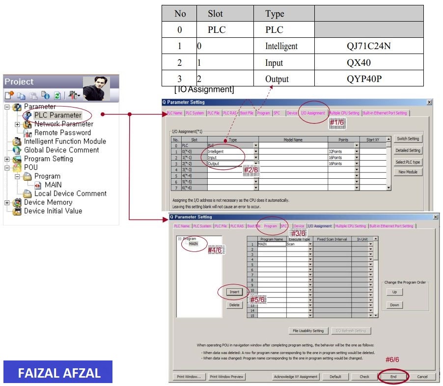
- Properly configure the I/O settings to include the QJ71C24N module within your PLC setup.
- Step 3: Channel 2 (RS485) Parameters Setting
- Configure the parameters for Channel 2, which will be used for RS485 communication.
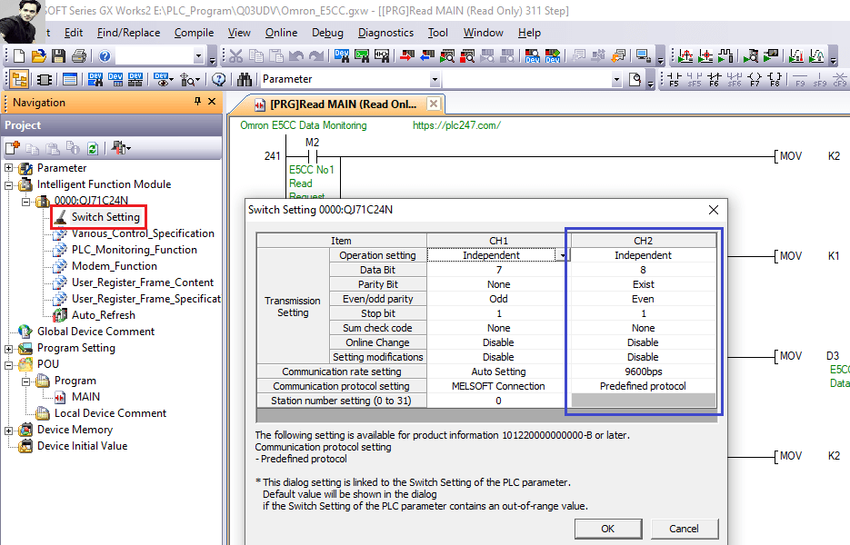
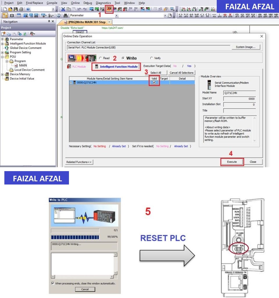
- Step 4: Write Parameters to Module QJ71C24N
- After configuring the necessary parameters, write them to the QJ71C24N module to activate the settings.
- Step 5: Disable Echoback
- Echoback refers to a function where data transmitted by RS485 is echoed back to the local station. To disable this feature:
- Set G450 = 1 (Disable Echoback)
- Set G450 = 0 (Enable Echoback, if needed)

4. QJ71C24N & Siemens V20 Modbus Configuration
Now, we will delve into configuring the actual Modbus communication protocols for reading and writing data to the Siemens V20.
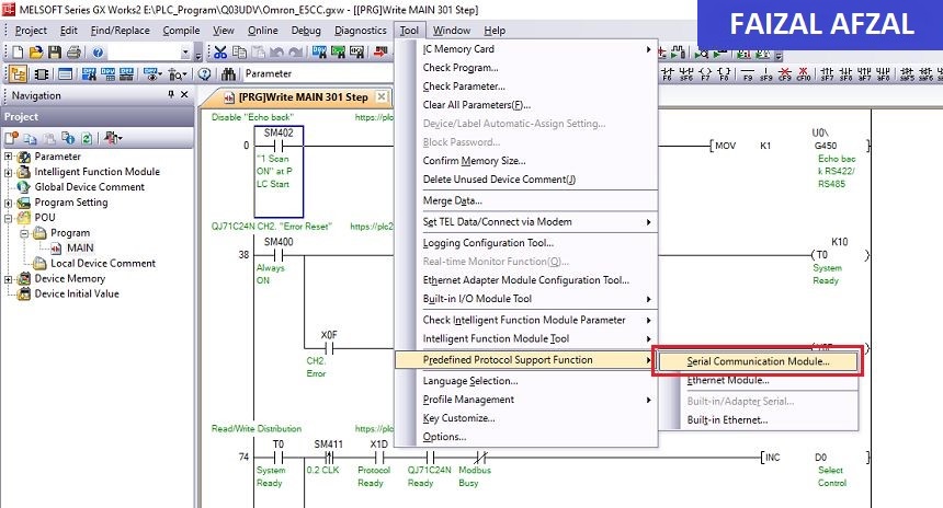
Configuration via Serial Communication Module Tool:
+Go to Serial Communication Module Tool
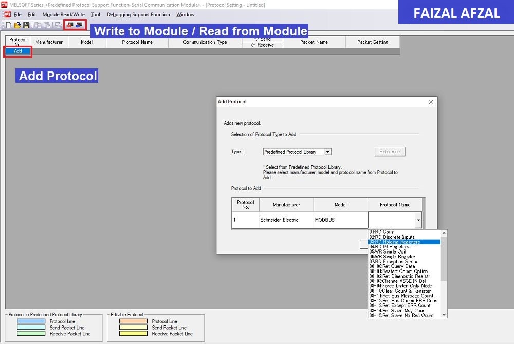
+ Protocol Add/Read/Write
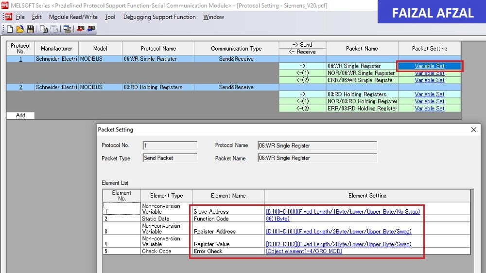
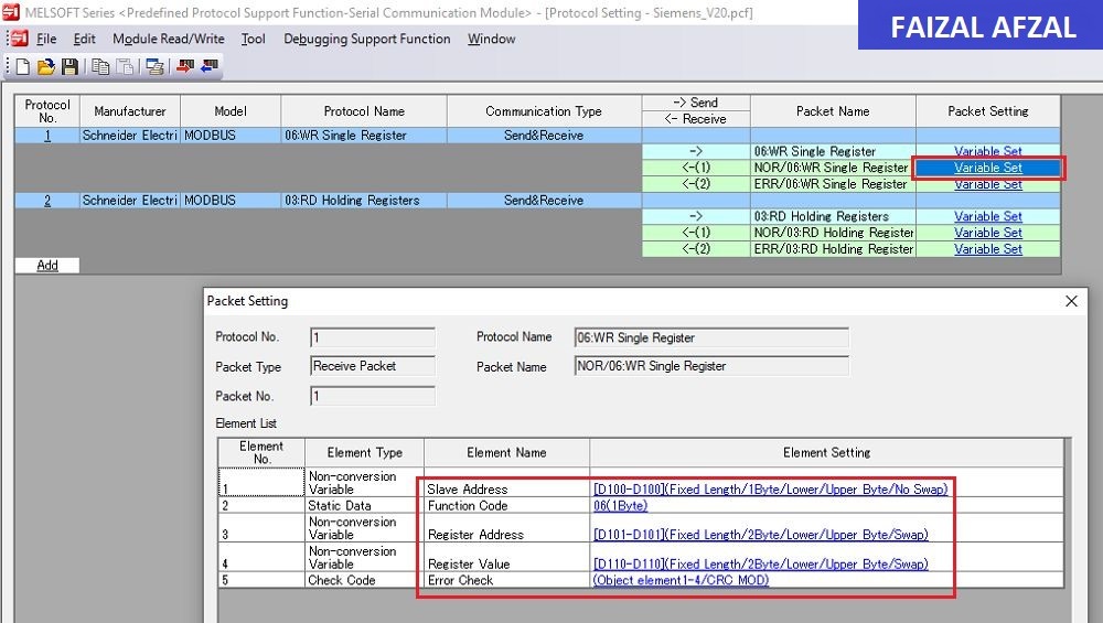
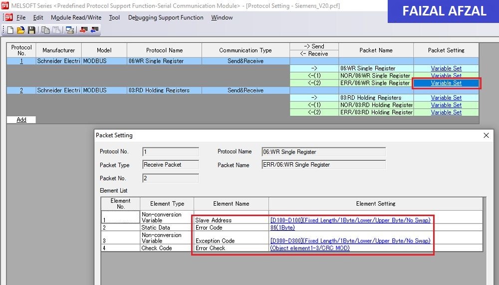
- Protocol No.1: Write Single Registers
- Function Code:
06 (Write Single Register) - Slave Address:
D100 - Register Address:
D101 - Register Value:
D110 - Communication Error:
D300
- Function Code:
- Protocol No.2: Read Holding Registers
-
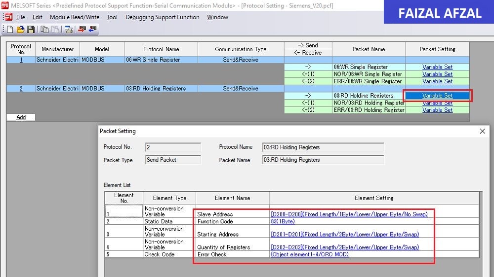
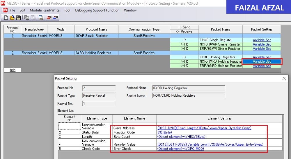
- Function Code:
03 (Read Holding Registers) - Slave Address:
D200 - Starting Address:
D201 - Quantity of Registers:
D202 - Registers Value Response:
D210(Stores values from D210 onwards depending on the number of registers read) - Communication Error:
D300
- Function Code:
-
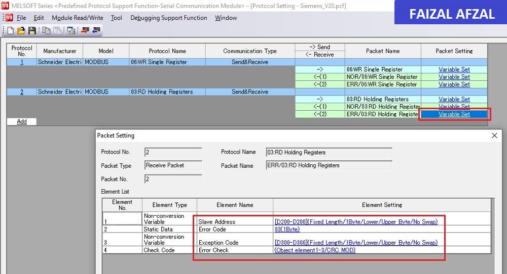
Note: Set an appropriate “Receive Wait Time” to avoid infinite wait loops in case of communication errors.
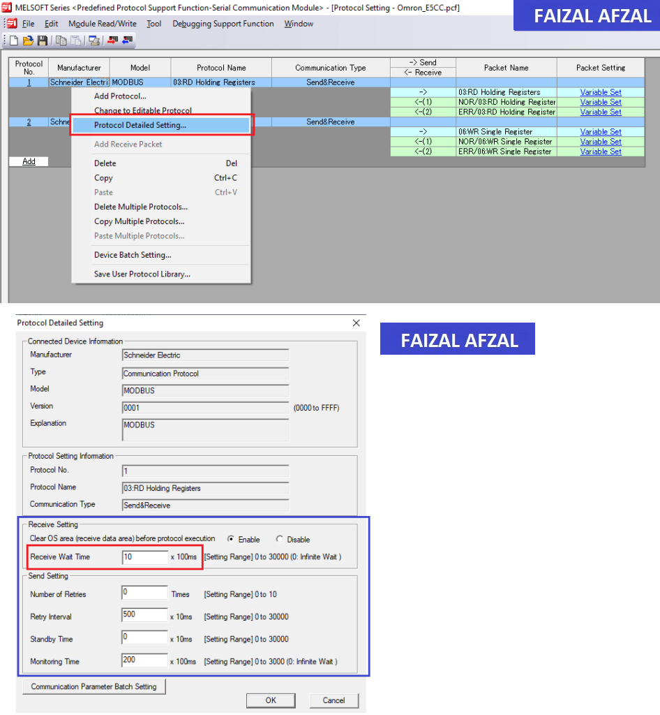
Modbus Configuration in Serial Communication Module Tool
5. PLC Programming Example
To finalize the setup, we will create a sample program in the PLC to handle the communication and control of the V20 inverter.
Sample Program Breakdown:
- Disable Echoback & Error Clear:
- Initialize the system and clear any previous errors before starting communication.
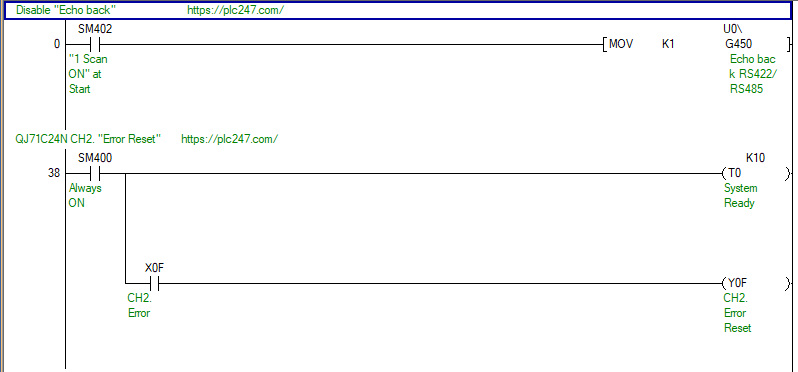
- Communication Distribution:
-
- Distribute the communication tasks across different channels or devices as required.
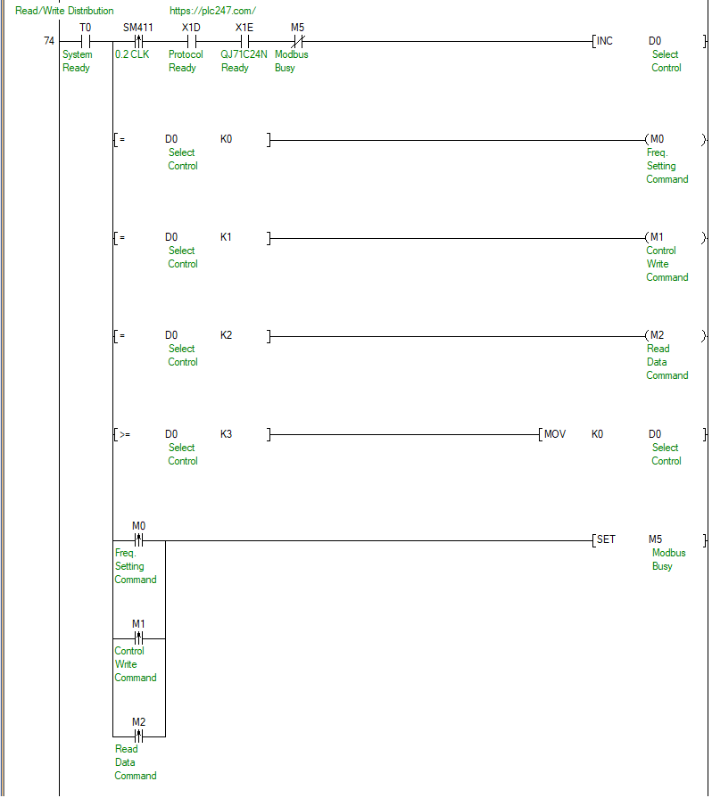
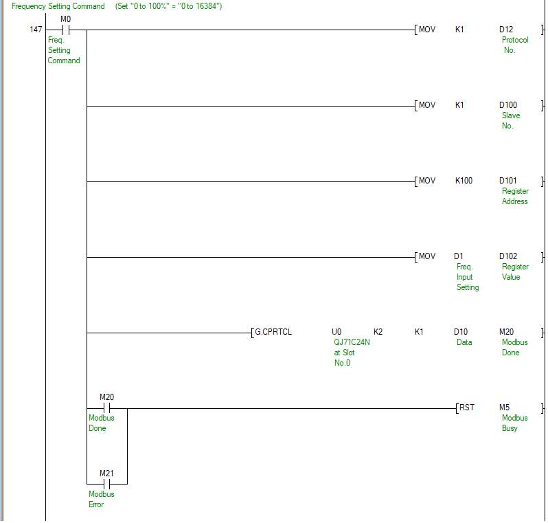
- Frequency Setting Command:
-
- Send the frequency setting to the V20 inverter based on the operational requirements.
- VFD Control Command:
-
- Execute the necessary control commands (e.g., Forward Run, Reverse Run, Stop) based on the input conditions.
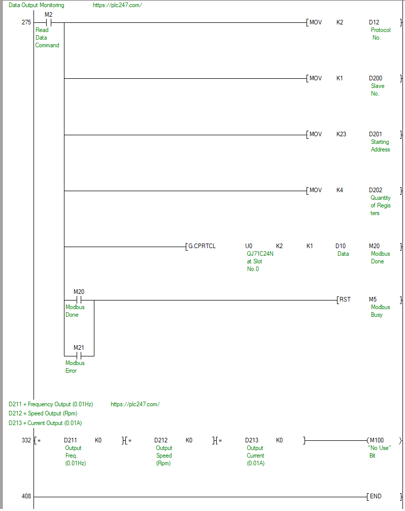
Read Data Monitoring:
-
- Continuously monitor the response from the V20 inverter, including speed, frequency, and current values.
Conclusion
By following this detailed guide, you will successfully configure and control the Siemens Sinamics V20 inverter using the Mitsubishi QJ71C24N module through the Modbus RTU protocol. This tutorial provides a step-by-step approach to ensure a smooth setup process, covering connection diagrams, Modbus configuration, and practical PLC programming examples. For additional support, refer to the images and examples provided throughout the tutorial to enhance your understanding and implementation.