MicroLogix 1400 “Modbus RTU” Control of Delta VFD-M
Introduction
The Delta VFD-M series, though discontinued and replaced by newer models like the MS300, remains a prevalent choice in industrial machinery. Due to its widespread use, there are still many instances where engineers and technicians need to interface with this older inverter model. This guide will walk you through the process of using a MicroLogix 1400 PLC to control a Delta VFD-M inverter via Modbus-RTU (RS485) communication.
This tutorial provides detailed instructions on wiring, parameter configuration, and programming to ensure a seamless and efficient setup.
1. MicroLogix 1400 & Delta VFD-M Wiring Diagram
To begin, you need to establish the correct wiring connections between the MicroLogix 1400 PLC and the Delta VFD-M inverter. The preferred method is using the 1763-NC01 module for easy wiring; however, direct connections to the RS485 port of the MicroLogix 1400 PLC (Mini DIN – 8 Pin) are also possible.
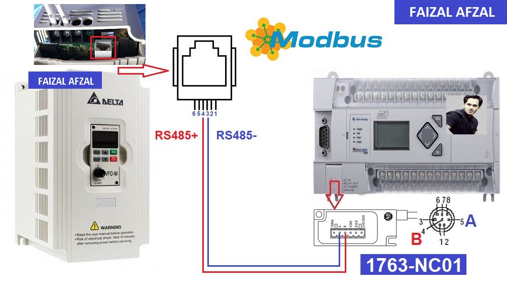
MicroLogix 1400 & Delta VFD-M Wiring Diagram
Wiring Tips:
- RS485 Communication: Ensure proper connection of the RS485 communication lines to avoid any transmission errors.
- Power Connections: Both the VFD and PLC should be correctly powered and grounded according to the manufacturer’s specifications.
2. Delta VFD-M Parameter Configuration
For successful communication and control of the Delta VFD-M via Modbus-RTU, certain parameters need to be configured on the inverter. These configurations align the VFD’s communication settings with those of the MicroLogix 1400 PLC.
Essential Parameter Configurations:
- Pr00: = 03 (Frequency Setting via RS485)
- Pr01: = 04 (Motor Control via RS485)
- Pr88: = 01 (Modbus Slave Address)
- Pr89: = 01 (Baud Rate: 9600bps)
- Pr92: = 04 (Modbus RTU Configuration: 8-bit, 1 stop bit, Even parity)
- Pr157: = 01 (Modbus RTU Selection)
These parameters ensure that the Delta VFD-M is properly set up to receive and respond to commands from the MicroLogix 1400 PLC via Modbus-RTU.
3. Delta VFD-M Registers Address for Control
Controlling the Delta VFD-M involves writing specific values to its Modbus registers. Here, we will cover the main register addresses used for motor control and frequency setting.
Motor Control Register Address:
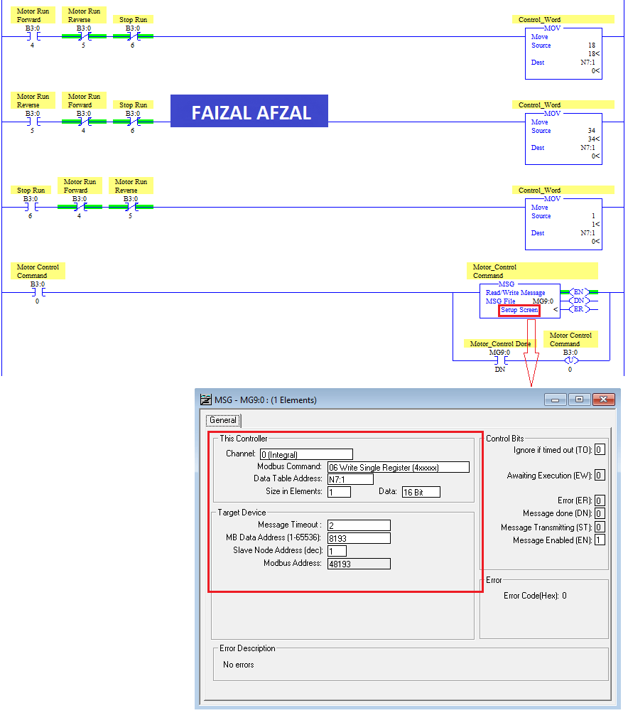
- Control Motor: 2000 (Hex) + 1 = 8192 (Dec) + 1 = 8193 (Dec)
- Run Forward: Set Word 8193 = 0000 0000 0001 0010 (Binary) = 12 (Hex) = 18 (Dec)
- Run Reverse: Set Word 8193 = 0000 0000 0010 0010 (Binary) = 22 (Hex) = 34 (Dec)
- Stop Command: Set Word 8193 = 0000 0000 0000 0001 (Binary) = 01 (Dec)
Frequency Setting Register Address:
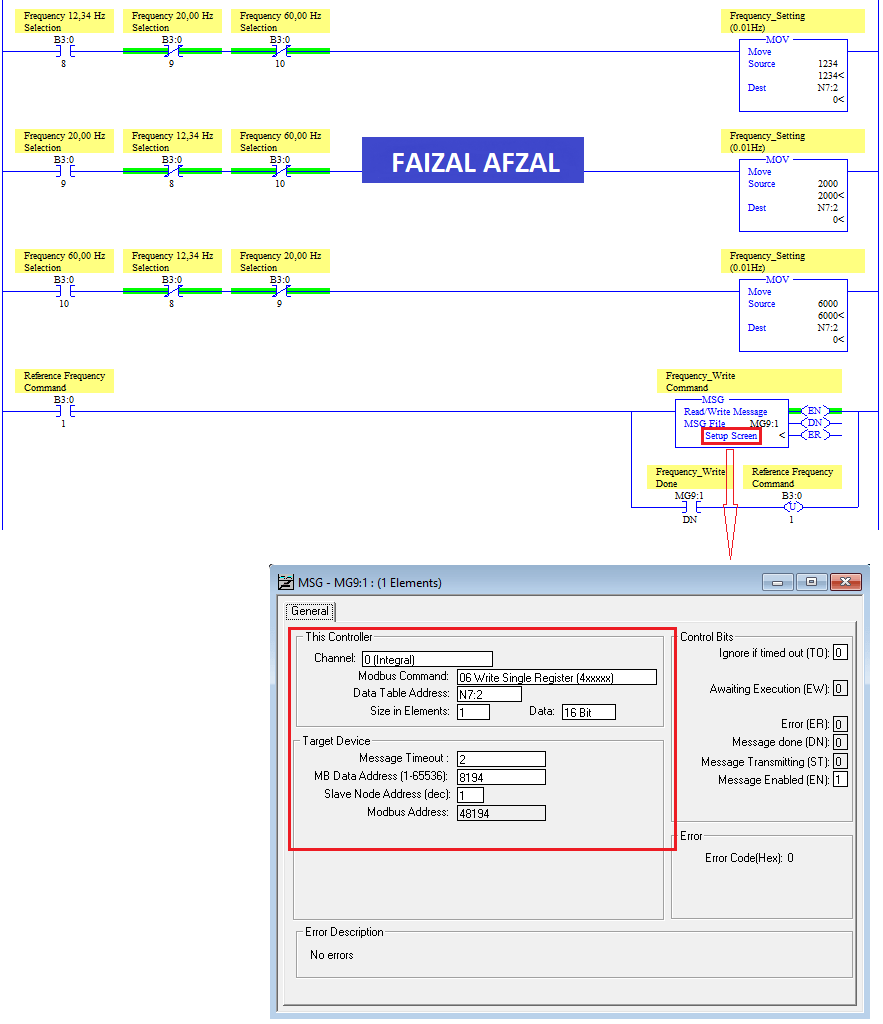
- Setting Frequency: 2001 (Hex) + 1 = 8193 (Dec) + 1 = 8194 (Dec)
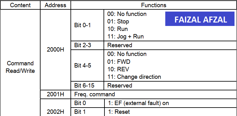
Delta VFD-M Control Register Table
These register addresses and corresponding values allow you to control the basic operations of the VFD, such as starting, stopping, and adjusting the motor speed.
4. Delta VFD-M Registers Address for Monitoring
Monitoring the Delta VFD-M’s performance involves reading specific output registers. These registers provide real-time data on various operational parameters, including frequency, current, and voltage.
Monitoring Register Addresses:
- Start Reading Address: 2102 (Hex) + 1 = 8450 (Dec) + 1 = 8451 (Dec)
Faizal Afzal recommends reading five output registers to monitor:
- Frequency Command
- Output Frequency
- Output Current
- DC-BUS Voltage
- Output Voltage
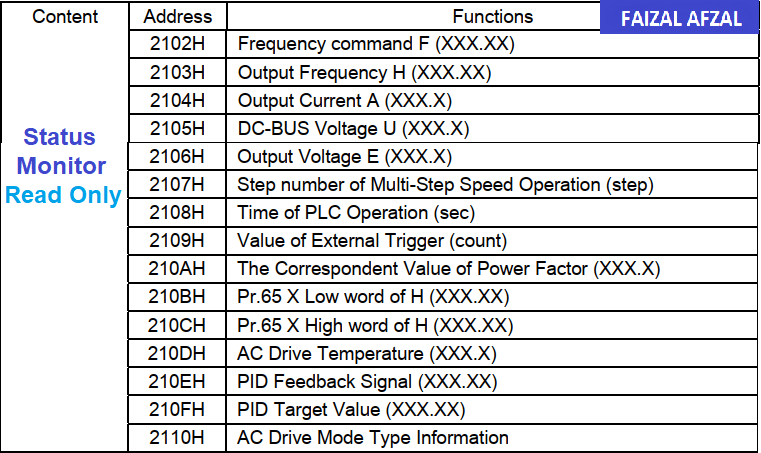
Delta VFD-M Monitoring Register Table
These monitoring addresses are essential for tracking the VFD’s operational status and ensuring it functions correctly within the desired parameters.
5. MicroLogix 1400 Modbus RTU Configuration
To establish communication between the MicroLogix 1400 PLC and the Delta VFD-M, you need to configure Channel 0 on the PLC for RS485 communication. The settings must match the communication parameters set on the VFD.
Channel 0 (RS485) Configuration Steps:
- Set the communication protocol to Modbus RTU.
- Match the Baud Rate with the VFD (9600bps).
- Configure Data Bits to 8, Stop Bit to 1, and Parity to Even.
- Assign the correct Node Address that corresponds with the VFD.
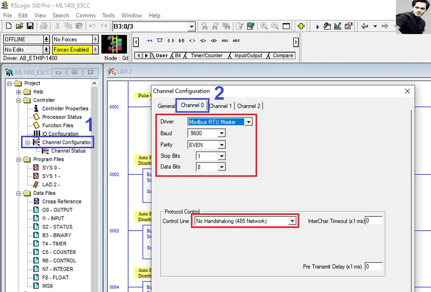
MicroLogix 1400 RS485 Configuration Screen
Proper configuration ensures that the MicroLogix 1400 PLC can successfully communicate with and control the Delta VFD-M.
6. MicroLogix 1400 PLC Programming
Finally, you will need to program the MicroLogix 1400 PLC to handle both the control and monitoring tasks for the Delta VFD-M. Below are the critical programming components required for effective VFD management.
Programming Components:
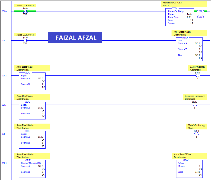
- Read/Write Auto Communication:
- Develop logic to automate the reading and writing of data between the PLC and the VFD.
- VFD Control Command:
-
- Program the PLC to send control commands such as start, stop, forward, and reverse to the VFD.
- Frequency Setting Command:
-
- Implement logic to adjust the motor speed by setting the desired frequency on the VFD.
- Data Output Monitoring:
-
- Set up routines to continuously monitor the VFD’s operational data and respond to any changes or faults.
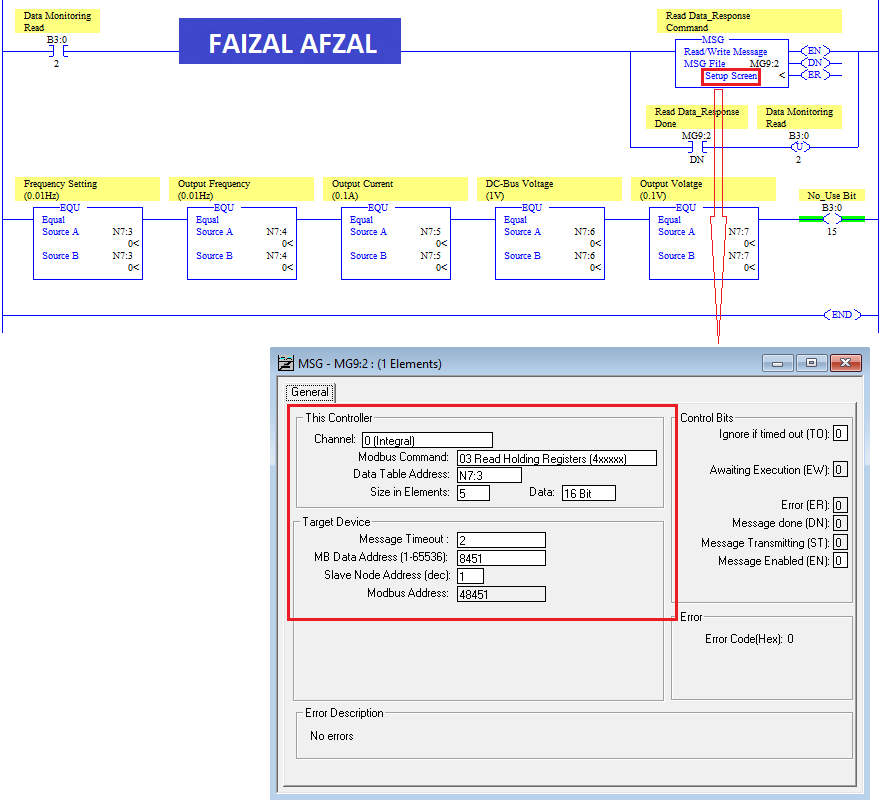
These programming steps integrate the control and monitoring of the Delta VFD-M into your automation system, providing seamless operation and feedback.
Conclusion
This professional guide provides a comprehensive approach to controlling the Delta VFD-M using a MicroLogix 1400 PLC via Modbus-RTU communication. From wiring and parameter configuration to PLC programming, each step is designed to ensure that you can efficiently and effectively manage the VFD within your industrial processes.
By following this guide, you will be able to maintain and control older Delta VFD-M inverters, ensuring continued reliability and performance in your operations.