Mitsubishi QJ71C24N Modbus RTU Communication with Danfoss FC51 Tutorial
Introduction
The Danfoss FC51 series of inverters, renowned for their powerful features, high durability, and compact size, have become a trusted choice for various industrial applications such as pumps, fans, conveyors, and cooling towers. They are also widely utilized in the HVAC and OEM sectors. In addition to its standard control methods, the Danfoss FC51 inverter supports the Modbus RTU communication protocol. This tutorial will guide you through the process of controlling the Danfoss FC51 using a Mitsubishi Q-Series PLC equipped with the QJ71C24N communication module.
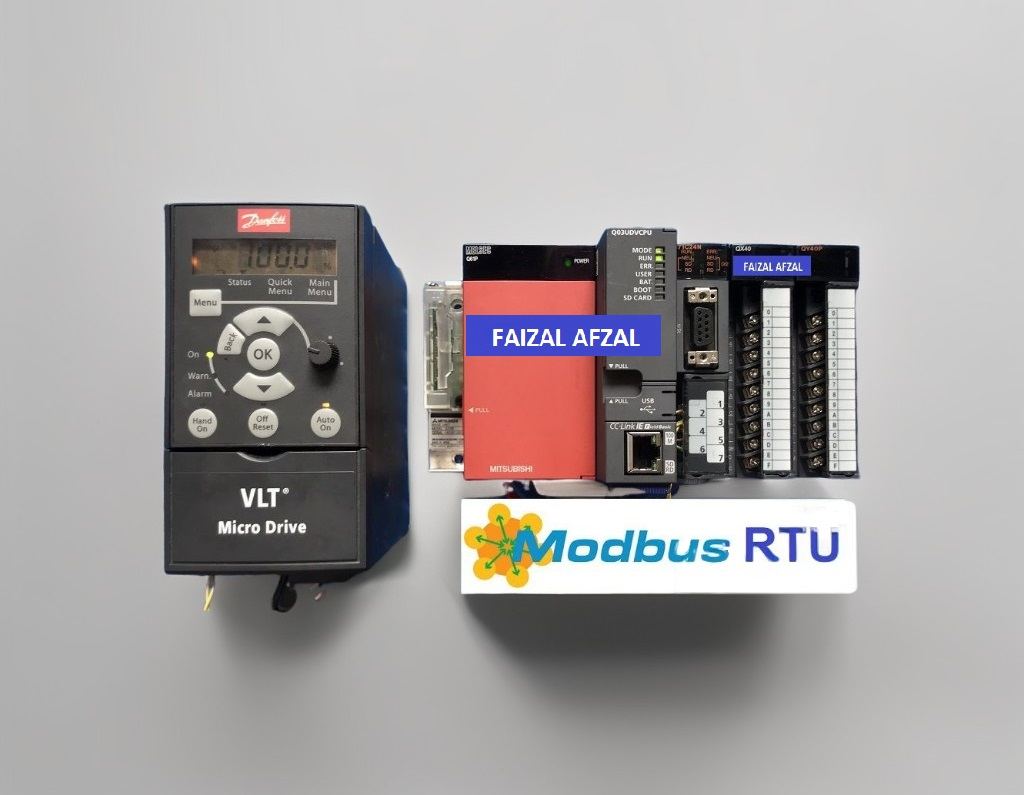
1. QJ71C24N & Danfoss FC51: Wiring Diagram
The Danfoss FC51 inverter comes with a built-in RS485 communication port, which simplifies the connection process with the Mitsubishi QJ71C24N module. Below is a wiring diagram illustrating the correct connections between these devices.
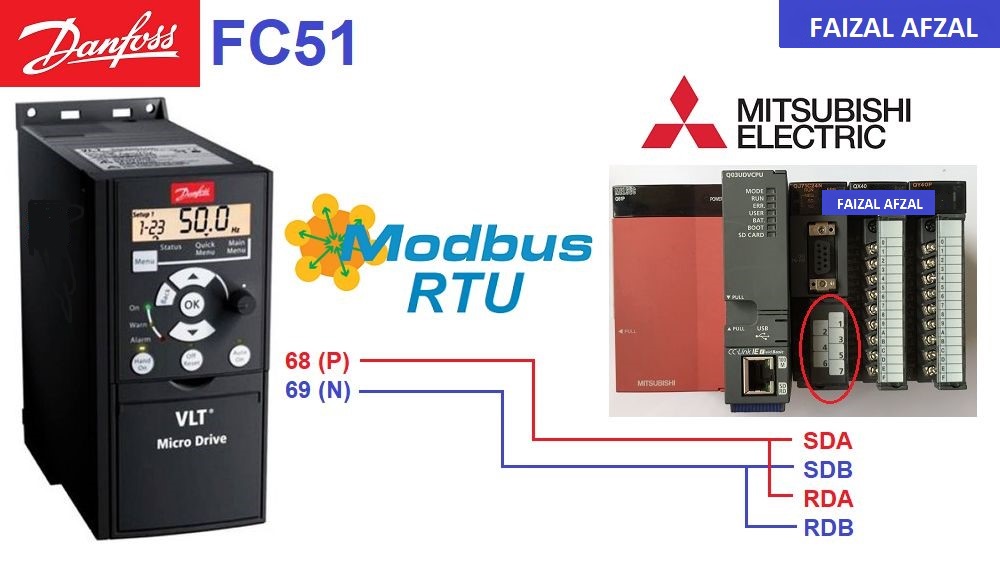
Wiring Diagram for QJ71C24N and Danfoss FC51
Explanation:
- RS485 Communication Port: The RS485 port on the Danfoss FC51 inverter allows for straightforward connectivity with the QJ71C24N module, ensuring reliable data transmission.
2. Danfoss FC51 Modbus RTU Parameters Setting
To control the Danfoss FC51 inverter via Modbus RTU, specific communication parameters must be configured in addition to the standard motor-related settings such as frequency, current, and voltage.
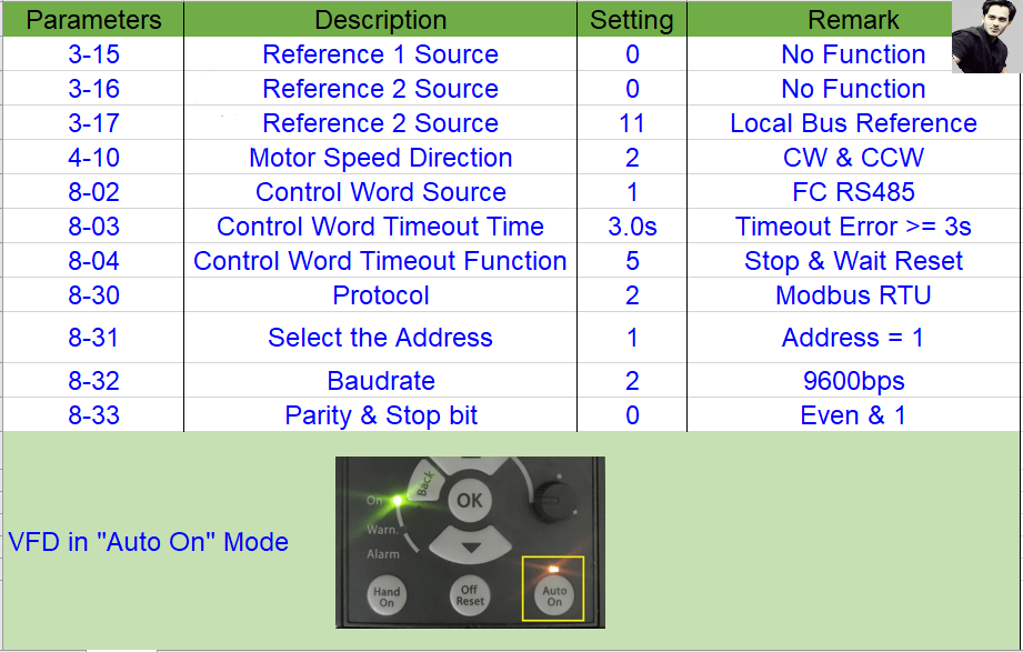
Key Modbus RTU Parameter Settings:
- VFD Control Address:
C34F (hex)- Forward Run: Set Register
C34F = 47C (hex)or1148 (dec) - Reverse Run: Set Register
C34F = 847C (hex)or33916 (dec) - Stop: Set Register
C34F = 43C (hex)or1084 (dec) - VFD Reset: Set Register
C34F = 4BC (hex)or1212 (dec)
- Forward Run: Set Register
- VFD Frequency Setting Address:
C359 (hex)- Reference Setting:
0 to 16384 (dec)~(0 to 100%)
- Reference Setting:
- Monitoring Addresses:
- Output Voltage Address:
16119 (dec) - Output Frequency Address:
16129 (dec) - Output Current Address:
16139 (dec)
- Output Voltage Address:
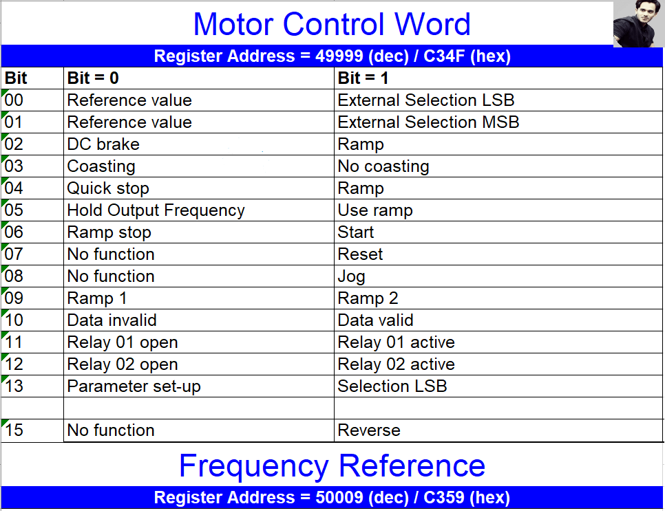
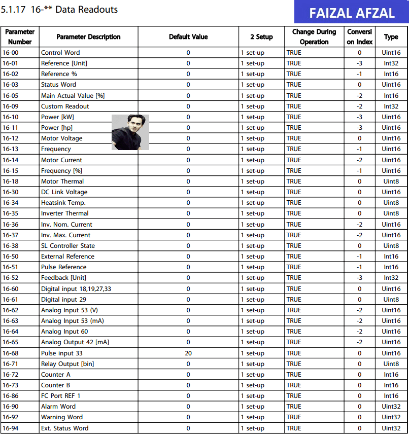
Danfoss FC51 Modbus RTU Parameter Settings
3. Mitsubishi QJ71C24N Modbus RTU Configuration
The next step is configuring the Mitsubishi QJ71C24N module to communicate effectively with the Danfoss FC51 via Modbus RTU.
Step-by-Step Configuration:
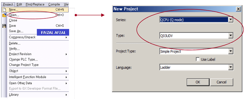
- Step 1: Create New Project
- Begin by creating a new project in your Mitsubishi PLC programming environment, tailored to your specific PLC model.
- Step 2: I/O Assignment
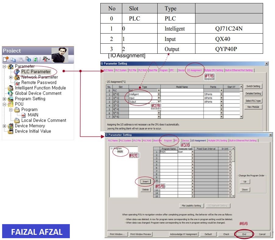
-
- Assign the I/O settings to include the QJ71C24N module in your PLC setup.
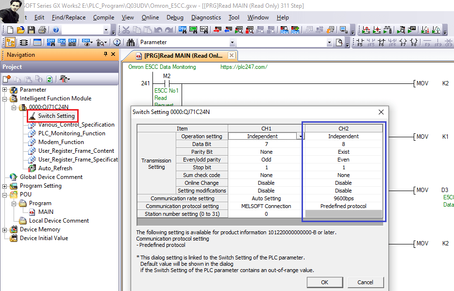
- Step 3: Channel 2 (RS485) Parameters Setting
-
- Configure the necessary parameters for Channel 2, which will handle RS485 communication.
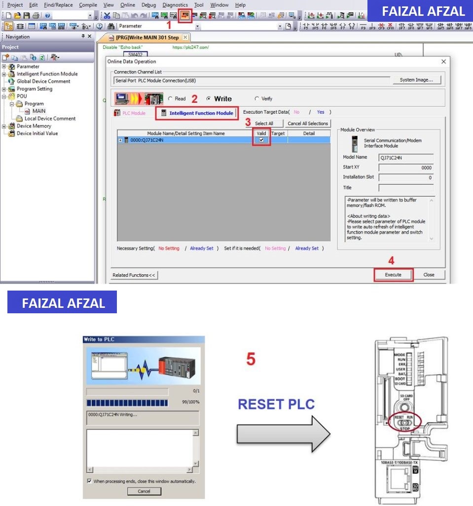
- Step 4: Send Parameters to QJ71C24N
-
- Once the parameters are set, write them to the QJ71C24N module to activate the configuration.
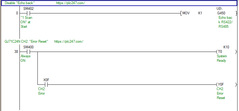
- Step 5: Disable Echoback
-
- Echoback is a function where data transmitted via RS485 is echoed back to the local station. Disable this feature by:
- Setting G450 = 1 (Disable Echoback)
- Setting G450 = 0 (Enable Echoback, if required)

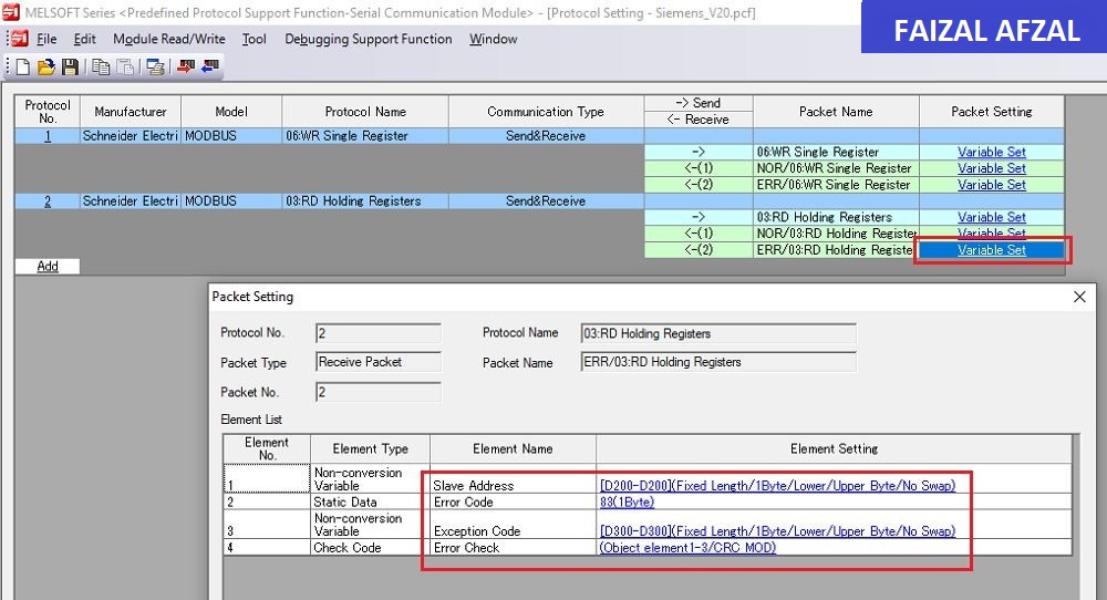
4. QJ71C24N Modbus RTU Protocols Configuration
After configuring the QJ71C24N module, the next step is setting up the Modbus RTU protocols for reading and writing data to the Danfoss FC51 inverter.
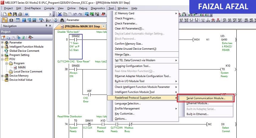
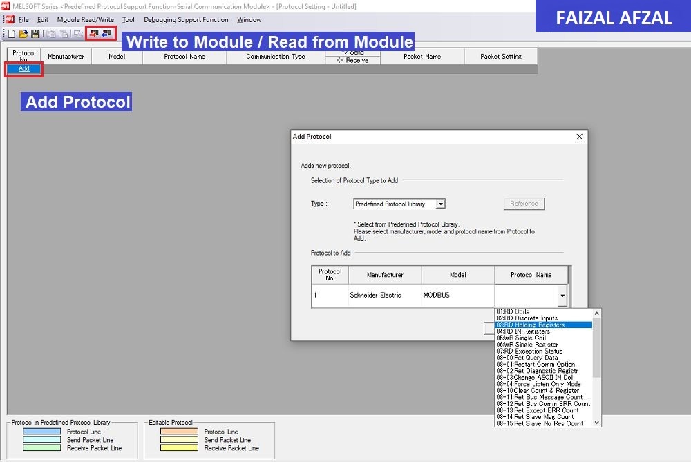
Configuration via Serial Communication Module Tool:
+Go to Serial Communication Module Tool
+ Protocol Add/Read/Write
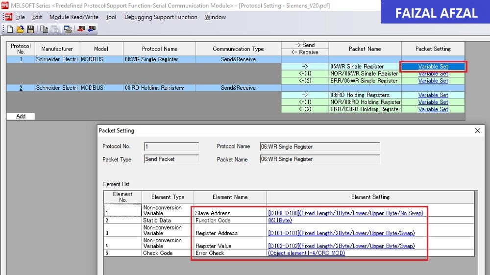
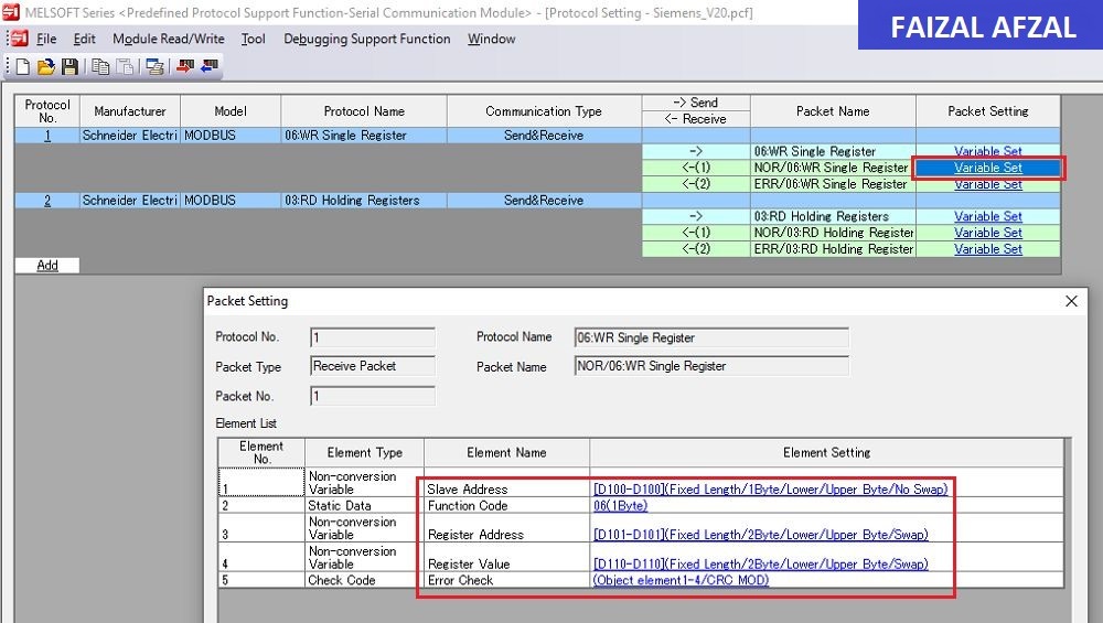
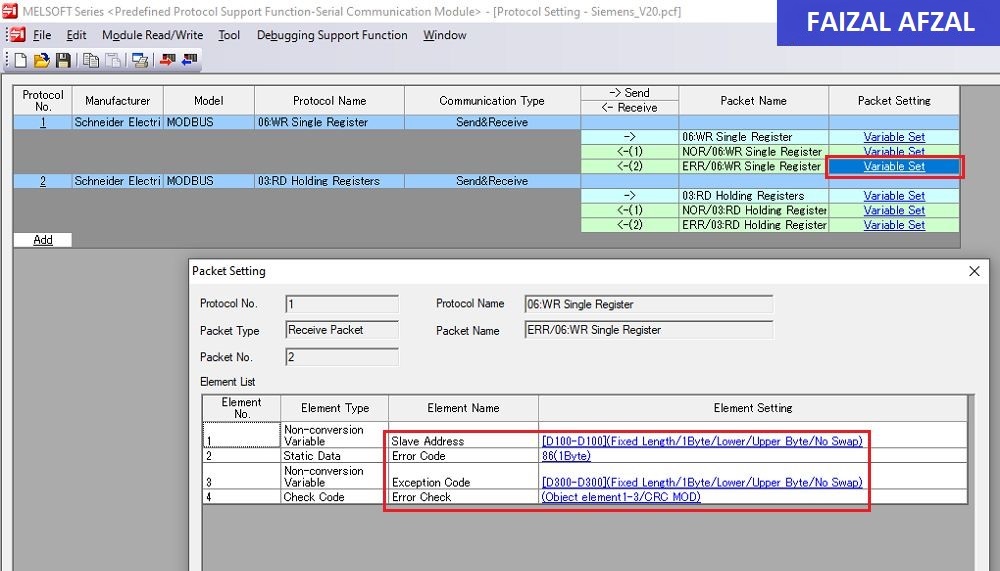
- Protocol No.1: Write Single Registers (Func 06)
-
- Slave Address:
D100 - Register Address:
D101 - Register Value:
D110 - Communication Error:
D300
- Slave Address:
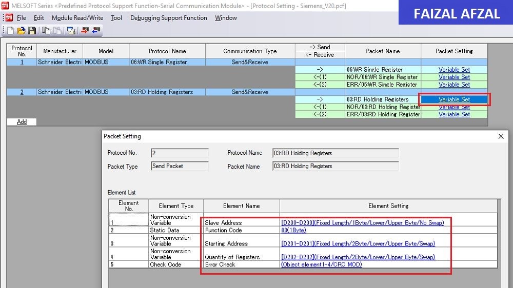
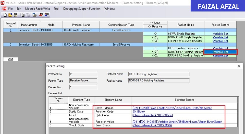
- Protocol No.2: Read Holding Registers (Func 03)
-
- Slave Address:
D200 - Starting Address:
D201 - Quantity of Registers:
D202 - Registers Value Response:
D210(From D210 onwards, depending on the number of registers read) - Communication Error:
D300
- Slave Address:
5. PLC Programming Example
With the configuration complete, the final step is to create a PLC program that controls the Danfoss FC51 inverter through the QJ71C24N module.
Sample PLC Program Overview:
- Disable Echoback & Error Clear:
- Initialize the system by disabling Echoback and clearing any previous errors to ensure smooth operation.
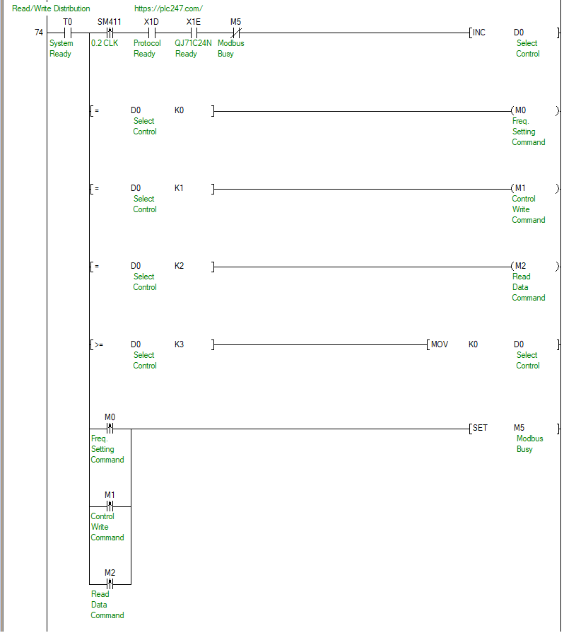
- Read/Write Distribution:
-
- Distribute read/write tasks across different communication channels or devices as necessary.
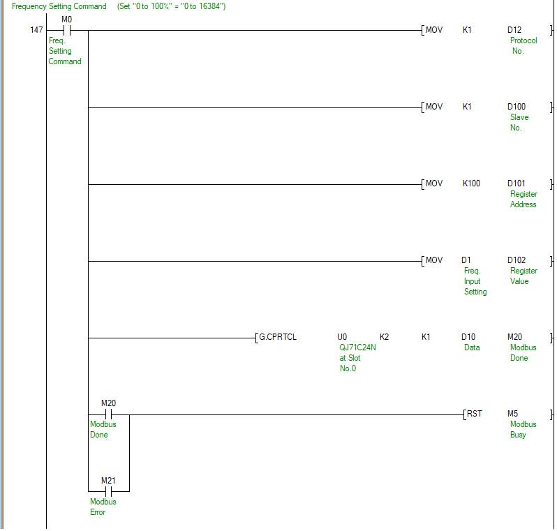
- Frequency Setting Command:
-
- Send the desired frequency setting to the Danfoss FC51 inverter.
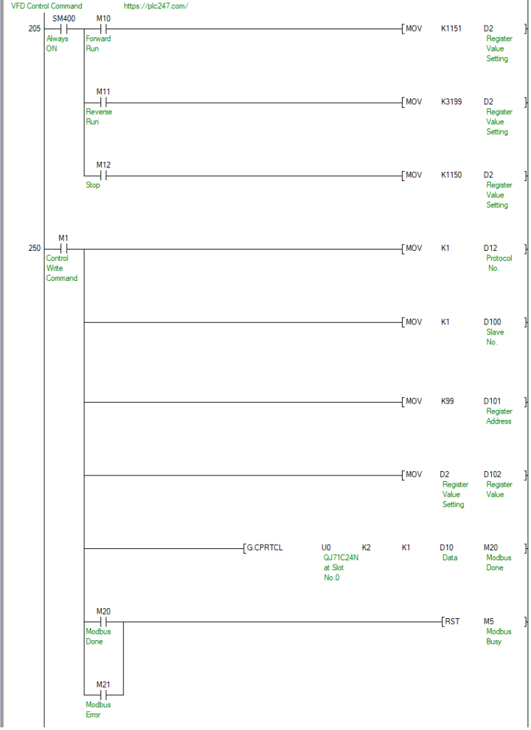
- VFD Control Command:
-
- Execute control commands such as Forward Run, Reverse Run, Stop, or Reset based on the operational requirements.
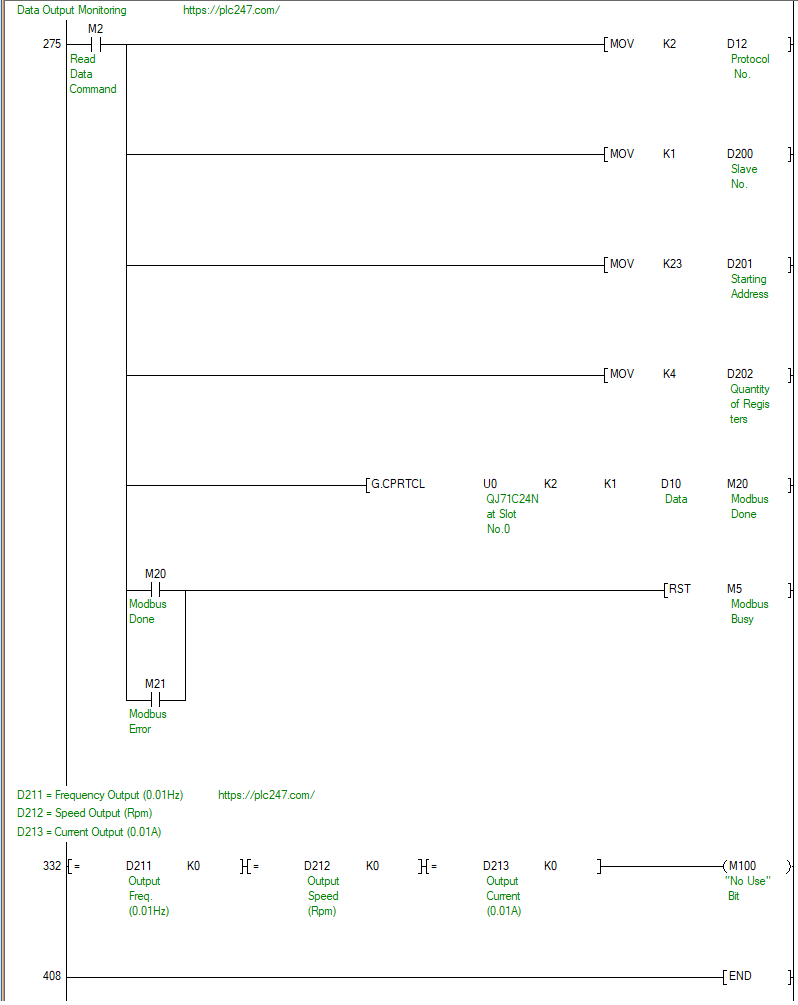
- Data Output Monitoring:
-
- Monitor output parameters such as voltage, frequency, and current to ensure the inverter operates within the desired range.
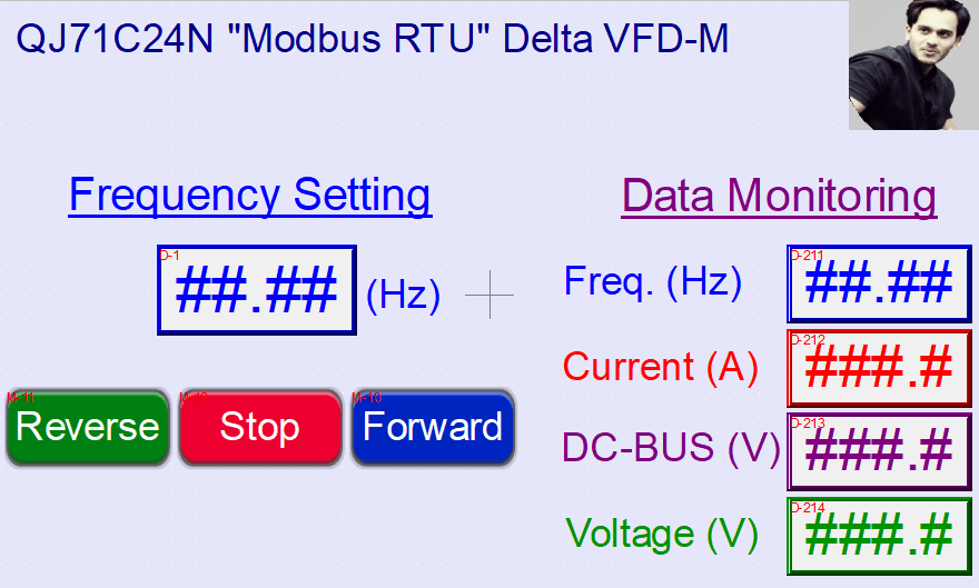
- HMI Interface:
-
- Implement an HMI interface to provide a user-friendly way to control and monitor the Danfoss FC51 inverter.
Conclusion
This detailed guide provides all the necessary steps to configure and control the Danfoss FC51 inverter using the Mitsubishi QJ71C24N module via the Modbus RTU protocol. The tutorial covers wiring diagrams, Modbus configuration, and practical PLC programming examples, ensuring a smooth and efficient setup. For a visual guide, refer to the images provided throughout the tutorial.