MicroLogix 1400 “Servo Control” with Mitsubishi MR-J4-A: A Comprehensive Tutorial
Authored by FAIZAL AFZAL
Introduction
This tutorial provides a step-by-step guide on how to use the Allen-Bradley MicroLogix 1400 PLC to control a Mitsubishi MR-J4-A Servo Motor. Designed for industrial automation enthusiasts and professionals alike, this guide aims to simplify the process, making it accessible even for those new to PLC programming and servo motor control.
The Allen-Bradley MicroLogix 1400 is a versatile and powerful PLC that, when combined with the Mitsubishi MR-J4-A Servo Motor, can handle complex motion control tasks with precision. This tutorial will walk you through the wiring setup, necessary configurations, and PLC programming required to achieve seamless control of your servo motor.
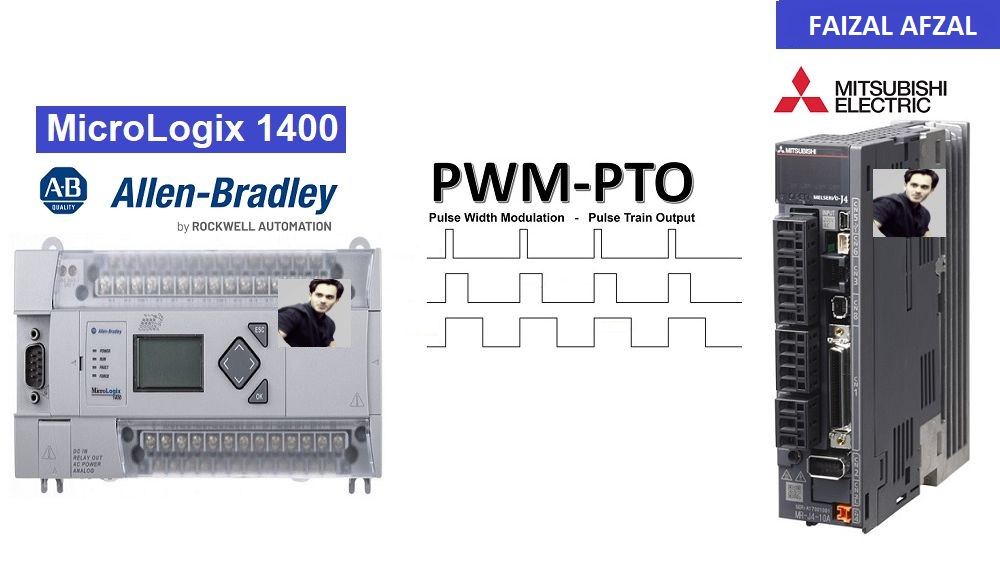
Step 1: MicroLogix 1400 & Mitsubishi MR-J4-A Servo “Wiring Diagram”
1.1 Overview of Wiring Connections
To control the Mitsubishi MR-J4-A Servo Motor with the MicroLogix 1400 PLC, it is essential to establish correct and reliable wiring connections. The wiring diagram below outlines the basic setup required to connect the PLC to the servo motor.
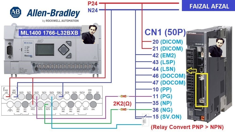
The wiring diagram between the MicroLogix 1400 PLC and the Mitsubishi MR-J4-A Servo Motor. Highlight connections for power, pulse, direction, and Servo ON/OFF control.
1.2 Key Wiring Details
- Voltage Reduction: Use a resistor with a value of 2.2kΩ to reduce the voltage from 24VDC to 5VDC for the pulse and direction signals. This ensures that the signals are within the acceptable range for the Mitsubishi MR-J4-A Servo Motor.
- Pulse Output (OUT2): Connect the OUT2 terminal of the MicroLogix 1400 PLC to the Pulse Pin of the MR-J4-A Servo Motor. This connection will deliver the pulse signals that control the motor’s movement.
- Direction Output (OUT3): Connect the OUT3 terminal to the Direction Pin of the servo motor. This connection dictates the direction of the motor’s rotation.
- Servo ON/OFF Control (OUT4): Connect the OUT4 terminal to the Servo ON/OFF control input of the MR-J4-A. This allows the PLC to enable or disable the servo motor as needed.
Step 2: Mitsubishi MR-J4-A Servo Driver Configuration
2.1 Configuring the MR-J4-A Servo Driver
The Mitsubishi MR-J4-A Servo Motor requires specific configuration settings to operate correctly with the MicroLogix 1400 PLC. These settings are adjusted using the MR-Configurator 2 software, which allows you to modify and fine-tune the servo motor’s parameters.
2.2 Key Parameters for Configuration
- PA1: Servo Control Mode Selection
- Setting:
1000 - Function: Selects the position control mode, essential for precise movement control based on pulse inputs.
- Setting:
- PA6/7: CMX/CDV (Input Pulse Gain Ratio)
- Default Setting:
1/1 - Function: Controls the ratio of input pulses to motor revolutions, ensuring that the servo motor interprets the pulse signals correctly. The default setting corresponds to
131072 pulses/revolution.
- Default Setting:
- PA13: PLSS (Selection of Control Pulse Types)
- Default Setting:
0100 - Function: Configures the type of control pulses that the servo will accept. The correct setting must be selected based on the pulse output method of the PLC.
- Default Setting:
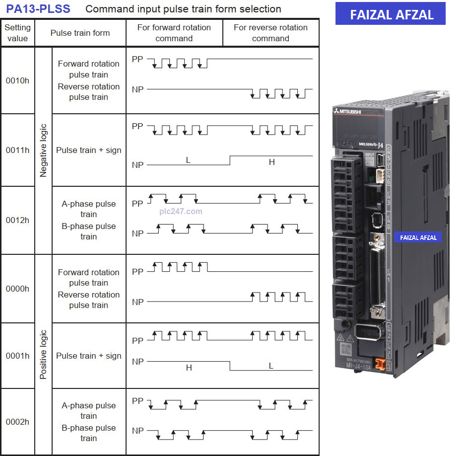
Table here that lists the various pulse input types and their corresponding settings
2.3 Recommended Settings for This Tutorial
For this tutorial, it is recommended that you use the following settings to ensure optimal performance:
- PA1:
1000(Position Control Mode) - PA6/7:
1/1(Default Pulse Gain Ratio) - PA13: Set according to the pulse type output from your PLC.
These settings will allow the Mitsubishi MR-J4-A Servo Motor to respond accurately to the control signals sent from the MicroLogix 1400 PLC.
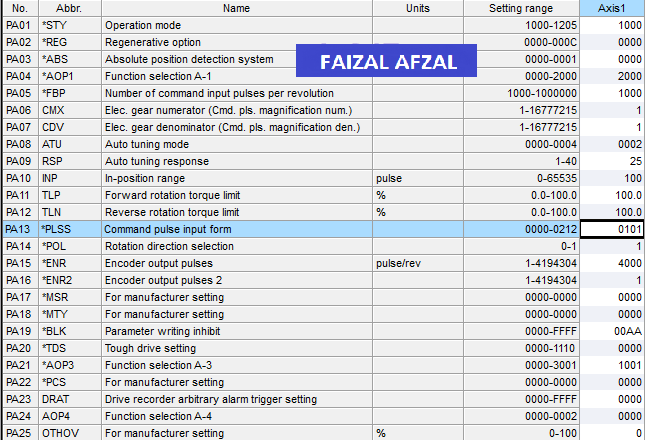
The key parameter values and their corresponding settings.
Step 3: MicroLogix 1400 “Position Control” Settings
3.1 Adjusting the PLC’s Output Settings
To successfully control the servo motor, it is crucial to adjust the output settings on the MicroLogix 1400 PLC. By default, the output settings are configured to -1, which will cause an error if not changed.
3.2 Key Settings for Output Configuration
- OUT2 (Pulse Generator): Change the output setting for OUT2 from
-1to2. This configuration sets OUT2 as the pulse generator, which sends the required pulse signals to the servo motor. - OUT3 & OUT4: Configure OUT3 and OUT4 for direction control and Servo ON/OFF control, respectively. These outputs must correspond to the physical wiring setup.
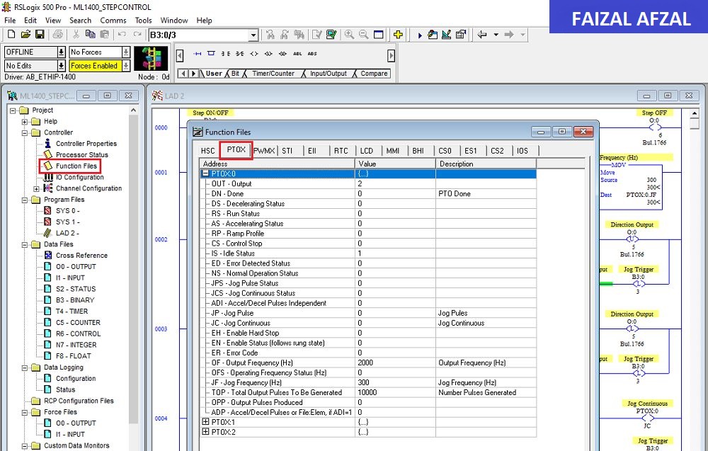
The output settings screen from the MicroLogix 1400 PLC interface, with annotations pointing out the necessary changes.
3.3 Position Control Overview
In this project, OUT2 is utilized as the primary pulse output, providing precise control over the servo motor’s position. The settings must be carefully configured to ensure that the pulse frequency and count align with the desired motor movements.
Step 4: PLC Programming for MicroLogix 1400
4.1 Introduction to PLC Programming
Programming the MicroLogix 1400 PLC involves writing logic that controls the servo motor’s movements, direction, and on/off states. In this section, we will discuss the essential programming steps required to achieve these control functions.
4.2 Servo Jog & ON/OFF Control
The program should include commands that allow you to jog the servo motor—moving it incrementally in either direction—and toggle its ON/OFF state. This is crucial for fine-tuning the motor’s position during setup and testing.
- Jog Control: Implement logic that sends short pulses to the servo motor, moving it incrementally in the desired direction.
- ON/OFF Control: Include a rung in your program that enables or disables the servo motor based on input conditions.
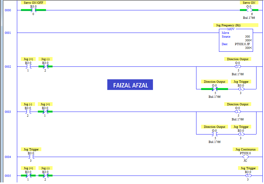
This is the control code snippet showing the ladder logic used in the RSLogix programming environment for jog and ON/OFF control.
4.3 Servo Position Control Programming
For precise position control, the PLC must send a specific number of pulses to the servo motor, causing it to move to the exact desired location.
- Position Command: Write logic that calculates the number of pulses required to reach a target position and then sends this number of pulses to the servo motor via OUT2.
- Direction Control: Ensure that the direction of the pulse output is controlled by the direction output (OUT3) based on the desired movement direction.
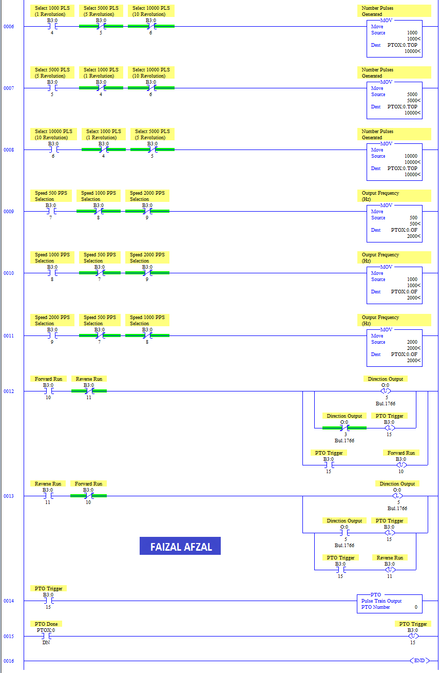
This is the code snippet showing the ladder logic used for position control in the RSLogix programming environment.
Conclusion
This comprehensive tutorial has provided detailed instructions on how to control a Mitsubishi MR-J4-A Servo Motor using the Allen-Bradley MicroLogix 1400 PLC. By following the steps outlined, you can achieve precise and reliable control over your servo motor, enhancing your automation capabilities.
For further learning, consider exploring more advanced PLC programming techniques and integrating additional sensors or control devices into your system to expand its functionality.
For further assistance or more detailed information, please refer to the Mitsubishi manuals or contact a Mitsubishi Electric support representative.