Mitsubishi FX5U Servo Control: MR-J4-A Tutorial
Written by FAIZAL AFZAL
Introduction
The Mitsubishi FX5U is a powerful and versatile PLC (Programmable Logic Controller) widely used in industrial automation. This tutorial provides a detailed guide on how to use the FX5U to control a Mitsubishi MR-J4-A series servo motor. By following this tutorial, you will learn how to establish a connection between the FX5U PLC and the MR-J4-A servo motor, configure essential parameters, and write the necessary programming instructions to control the servo motor effectively.
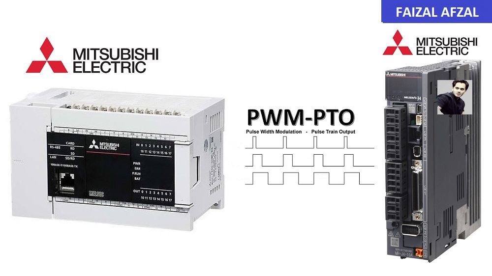
Wiring Diagram: Mitsubishi FX5U & MR-J4-A Servo Motor
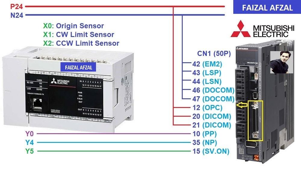 A detailed wiring diagram showing the connection between the Mitsubishi FX5U PLC and the MR-J4-A Servo Motor. This diagram clearly display the connections for power, inputs, outputs, and communication interfaces.
I/O Address Table
To ensure seamless communication between the FX5U PLC and the MR-J4-A Servo Motor, it is crucial to correctly map the input and output addresses. Below is the I/O address table for this setup:
Input Signals
- X0: Origin Sensor (Org Sensor)
Detects the home or origin position of the servo motor. - X1: Forward Limit Sensor
Monitors the forward travel limit to prevent the servo motor from exceeding its operational range. - X2: Reverse Limit Sensor
Monitors the reverse travel limit to protect the motor from exceeding its backward range.
Output Signals
- Y0: Pulse Output
Sends pulse signals to the servo motor driver for positioning control. - Y4: Direction Output
Determines the direction of rotation (clockwise or counterclockwise) for the servo motor. - Y5: Servo ON/OFF
Controls the power state of the servo motor (enables or disables the motor).
Mitsubishi MR-J4-A Parameters Setting
To ensure the MR-J4-A Servo Motor operates correctly with the FX5U PLC, several key parameters must be configured. These settings can be applied either directly via the driver’s control panel or using the MR-Configurator2 software, which can be downloaded from the Mitsubishi Electric website.
Essential Parameter Settings
- PA1: Servo Control Mode Selection
- Value: Set to
1000 - Purpose: Selects the position control mode, which allows the servo motor to be controlled based on input pulses.
- Value: Set to
- PA6/7: CMX/CDV (Input Pulse Gain Ratio)
- Default Value:
1/1 - Purpose: Adjusts the number of pulses per revolution, matching the pulse output from the PLC to the servo motor’s expected input.
- Default Value:
- PA13.PLSS: Selection of Control Pulse Types
- Default Value:
0100 - Purpose: Configures the type of control pulses used for communication between the PLC and the servo motor. Adjust the settings based on the table provided below to select the appropriate control method.
- Default Value:
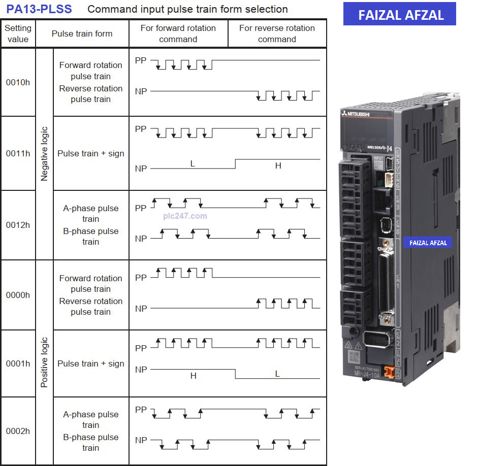
Table here that lists the various pulse input types and their corresponding settings
Recommended Parameter Configuration for This Project
For this tutorial, you can copy the following parameter values that have been specifically chosen for compatibility with the FX5U PLC and MR-J4-A servo motor:
- PA1:
1000 - PA6:
1 - PA7:
1 - PA13.PLSS:
0100
These settings will ensure the servo motor operates correctly under the control of the FX5U PLC.
FX5U Pulse Train Output Configuration
Configuring the FX5U for pulse train output is critical to ensuring that the PLC can effectively control the servo motor. This section covers the necessary settings and programming instructions.
Mitsubishi FX5U Programming Instructions
Below are the key programming instructions required for servo control:
1. Zero Return (Origin Return) Instruction
The Zero Return instruction is used to move the servo motor back to its origin or home position, a critical step in initializing the motor before operation.
- S1: ORG Sensor – This input device number corresponds to the origin sensor (X0).
- S2: Z-Phase Signal Input – This input device receives the Z-Phase signal from the servo motor.
- D1: Pulse Output Number – Specifies the output channel for pulse generation.
- D2: Rotation Direction Signal Output – Determines the direction of rotation during the return to origin.
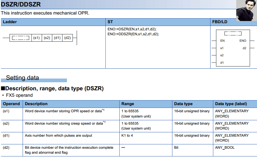 This image shows the Zero Return instruction implemented
2. Increment Pulse Output Instruction
This instruction allows the PLC to send a specific number of pulses to move the servo motor incrementally, step by step.
- S1: Number of Incremental Pulses – Defines the number of pulses to output for each incremental move.
- S2: Output Pulse Frequency – Sets the speed at which pulses are sent.
- D1: Pulse Output Number – Channel used for pulse output.
- D2: Rotation Direction Signal Output – Controls the motor’s rotation direction for each incremental move.
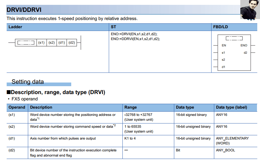
An example image of the Increment Pulse Output instruction
3. Absolute Pulse Output Instruction
The Absolute Pulse Output instruction is used for precise positioning, allowing the servo motor to move to a specific absolute position.
- S1: Number of Output Pulses – Represents the target absolute position.
- S2: Output Pulse Frequency – Determines the speed of movement.
- D1: Pulse Output Number – Specifies the pulse output channel.
- D2: Rotation Direction Signal Output – Controls the direction of movement.
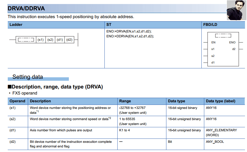
An example image of the Absolute Pulse Output instruction
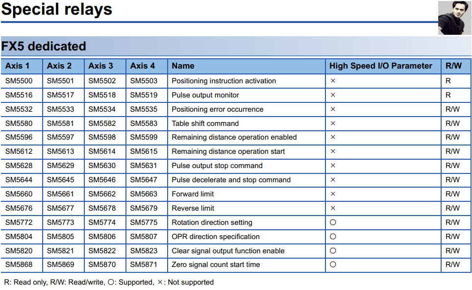
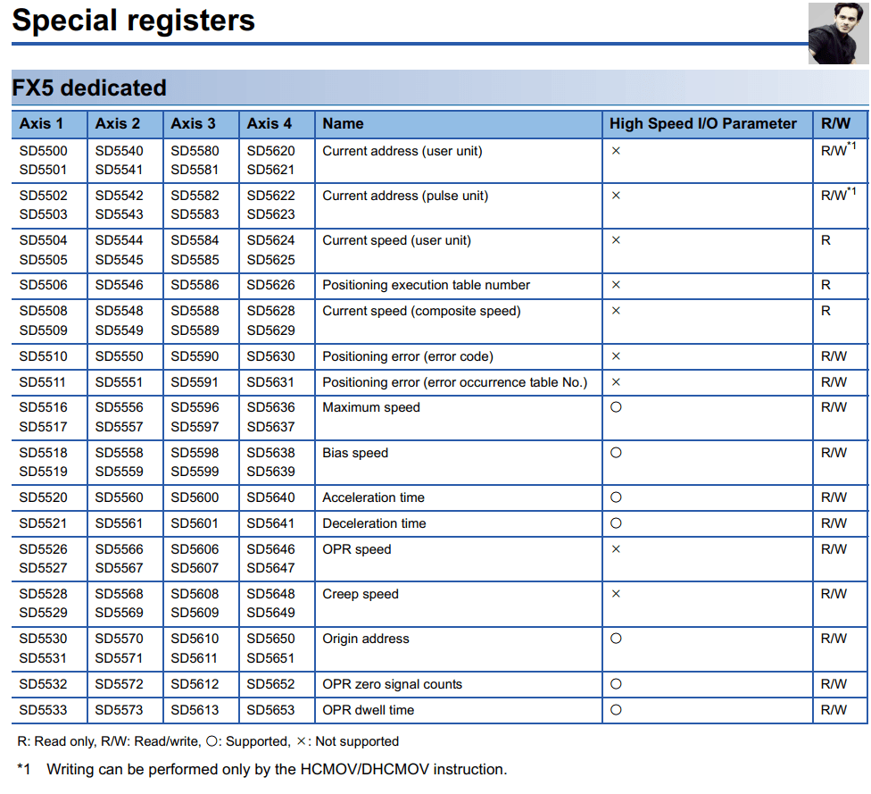
FX5U Special Relays & Registers
The FX5U PLC utilizes special relays and registers to handle high-speed operations and pulse output configurations. These special relays and registers must be configured correctly for the servo control to function smoothly.
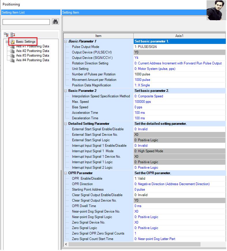
High-Speed I/O Setting
- Purpose: Configures the high-speed I/O channels for pulse output, ensuring the FX5U can generate the necessary pulses with minimal delay.
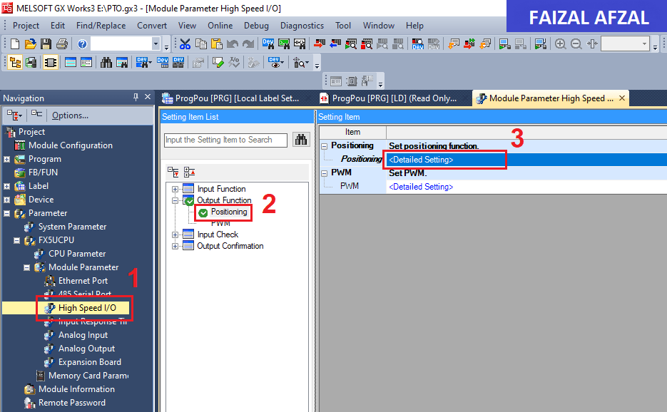
This image showing the configuration settings for high-speed I/O
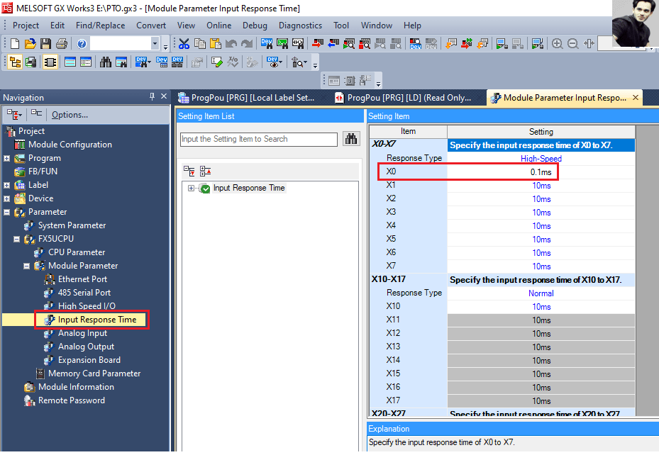
Input Response Time
- Purpose: Adjusts the input response time to synchronize the pulse output with the servo motor’s requirements, reducing the chances of missed signals or delayed responses.
This image showing the configuration settings for input response time.
FX5U Servo Control Programming
1. Servo ON/OFF & Zero Return Command
The first step in the programming process involves turning on the servo motor and sending it to its origin position. This ensures the motor starts from a known location, which is crucial for accurate positioning.
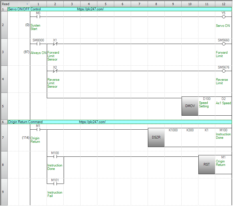
An image showing the ladder logic for Servo ON/OFF and Zero Return commands.
2. Jog Command
The Jog Command allows for manual or semi-automatic control of the servo motor, enabling fine adjustments to the motor’s position.
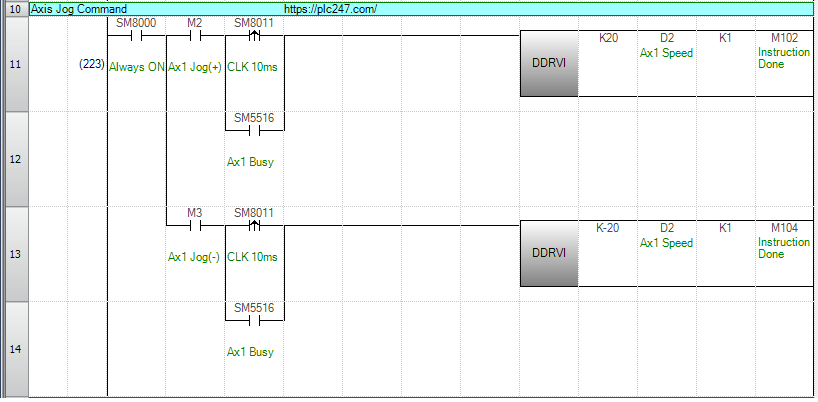
An image illustrating the Jog Command ladder logic
3. Control Position Command
This command is used to control the servo motor’s position based on predefined positions, allowing for accurate and repeatable movements.
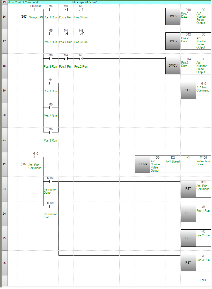
An image showing the ladder logic for the Control Position Command.
Conclusion
This tutorial has provided a detailed overview of how to control a Mitsubishi MR-J4-A Servo Motor using the FX5U PLC. By following the wiring diagrams, configuring the essential parameters, and implementing the programming instructions provided, you can achieve precise control over your servo motor. This guide is an excellent starting point for more advanced applications, where further customization and fine-tuning of the system can be explored.
For further assistance or more detailed information, please refer to the Mitsubishi manuals or contact a Mitsubishi Electric support representative.